What?
An attachment to a tap wrench that uses an IMU (inertial measurement unit), specifically the gyroscope part to track the angular position of the tap in space. A button and RGB LED allows the user to set the position by pressing the button, and the RGB LED provides feedback on how straight they are tapping through the hole by representing green for “aligned”, and becomes more red as they deviate from the true position they set by pressing the button. By finding the true position of the hole, a cone part is inserted into the tap wrench until it fits. Then, the user can set the position and produce a well-aligned tap.
Why?
When I took manufacturing in high school, we were taught how to do tapping manually. A critical aspect of tapping by hand is making sure that the tap is aligned to the hole, because you do not want a thread that goes sideways, especially when you screw in something. The Vertap project is directed towards high school students or anyone trying to learn manual tapping.
Process
The first step in the process was taking a tap wrench, and measuring its dimensions. This allowed to design and create the cone plunger part in SolidWorks
Next step was acquiring a microcontroller and IMU. For the prototype, I am using an Arduino Nano and a MPU-6050. I previously used a MPU-9250, another IMU produced by the same manufacturer.
Afterwards, the coding part comes along. I need to get the IMU outputting raw data and ensuring the data output makes sense (the gyroscope values spike when I shake the prototype)
To complete the prototype, I wire up a button and a RGB LED to the IMU. I also program it in the Arduino IDE. I program the button to set the position and the LED to change its colour to show how close you are to the position it was set to, as talked about in the “What?” section
Currently I am working on the project, I am thinking of creating a more advanced program and my own library for the IMU, to learn more about the entirety of the process of working with IMUs (reading datasheets, low-level programming, bit manipulation, etc.)
Images
Current Challenges
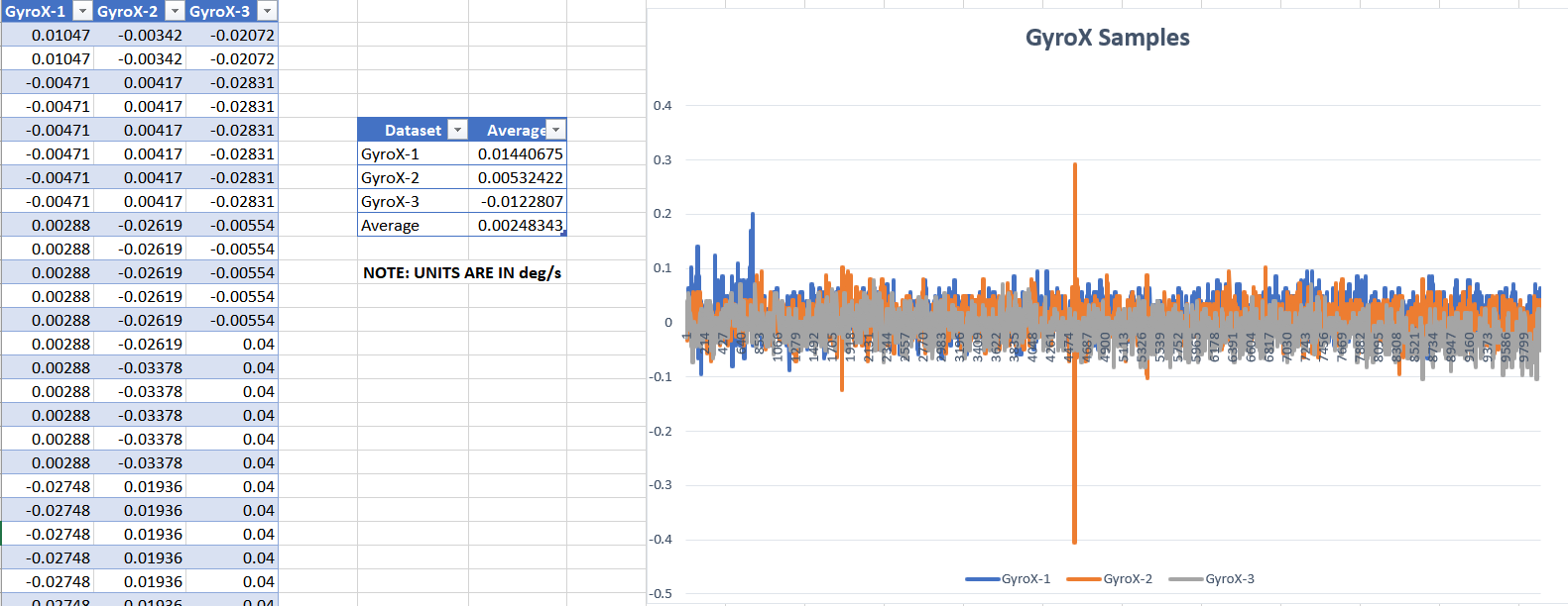
First challenge is filtering the raw data that the IMU outputs. Research has to be done (how they work, and how to implement). I am currently looking into Kalman filters, although that might be a little more complex
The RGB LED drastically changes from green to red, so an algorithm must be carefully designed to output the colours smoothly (no rough transitions). Since the IMU outputs raw data, the LED is susceptible to the noise from the gyroscope which could be one of the reasons with the LED issue
CURRENTLY WORK IN PROGRESS!
Stay updated on my Vertap project through my Twitter account!
